

Notes.
-

Coution
This manual is intended to provide an overview of installation procedures; actual installation requires specialized skills.
We recommend that you refer to the latest TESLA Service Manual and have a reliable professional store perform the installation. -
Warning!
This product contains nitrogen gas.
- Never attempt to disassemble the shock absorber as it is filled with high-pressure gas and is dangerous.
- Please ask a specialist such as a maintenance shop or auto dismantler to dispose of the shock absorber body as it is dangerous.
- Do not throw into fire.
- Keep away from fire or welding flame.
-

How to dispose of the shock absorber
Use a drill of 2 to 3 mm in diameter to drill a hole as shown in the illustration and vent the gas.
(Use a plastic bag to prevent chips from scattering, and be sure to wear protective goggles.) -
IMPORTANT
- Be sure to install this product as a front and rear set. The specified performance may not be achieved.
- Never extend or contract the damper part of the main body.
- Do not tighten the product when the vehicle is lifted. The effect of the product will not be properly demonstrated.
- Tighten bolts and nuts securely to the specified tightening torque.
- If necessary, retighten the bolts and nuts.
If any abnormality (abnormal noise, vibration, etc.) occurs during driving, immediately stop the car in a safe place, inspect the mounting bolts, etc., and retighten
. If the problem persists, inspect and repair the product immediately. Continued driving may cause
damage to the vehicle or an accident.


Components
- COX BODY DAMPER (for front: TMY-F) 1 piece
- COX BODY DAMPER (for rear: TMY-R) 1 piece
- Bracket (for front *for both right and left) 2 pieces
- Bracket (for rear *for both right and left) 2 pieces
- Cap screw (P1.5, half thread) 4 pieces
- Washer (M10) 4 pieces
- Collar: Outer diameter 28mm, thickness 7mm (for front) 4 pcs.
- Hex Bolt: 14mm diagonal with flange (M10x30) 4 pcs.
- Spacer: 6mm (M10-t6) 4 pcs.
- Lock Nut: Self Lock, 14mm diagonal (M10) 4 pcs.
- Color: Outer diameter 25 mm, thickness 9 mm (M10-t9)
- Color: Thickness 3 mm (M18-t3)
- Special nut
Front Installation Procedure

#1
Remove under Panel
Refer to the TESLA Service Manual to remove the front under panel to access the "crash can bracket" mounting bolts on the front side of the stabilizer mount.

#2
Remove bolts
Remove the two bolts attaching the "crash can bracket" to the front subframe.

#3
Prepare brackets
Prepare ”3.Brackets (for front)” ”8.collar" "6.Cap screw" "7.washer" referring to the image.

#4
Fix the Brackets
Fix the Brackets to the subframe referring to the image.
(Torque Value: 53 Nm)

#5 (Performance & RWD Only)
Fix the BODY DAMPER
for Performance & RWD Model
<Attention!> Watch the mounting position of the spacer!
Refer to the image and assemble "1.Body (for front)" with "9.M10×30 bolt", "10.Spacer" "11.Nut"
Adjusting the position so that the left and right sides are even. (Torque Value: 45 Nm)

#5 (LongRange Only)
Fix the BODY DAMPER
for LongRange Model Only
<Attention!> Watch the mounting position of the spacer!
Refer to the image and assemble "1.Body (for front)" with "9.M10×30 bolt", "10.Spacer" "11.Nut"
Adjusting the position so that the left and right sides are even. (Torque Value: 45 Nm)
Check the overall balance, assembly condition, etc., and fix the bracket securely according to the Torque Value of each bolt.
-

Completed Image 1
-

Completed Image2


Rere Installation Procedure

#1
Remove Rear Bumper
Refer to the TESLA Service Manual to remove the Rear bumper to access the "Bumper Beam".
(Image shows only the diffuser removed, but the bumper must be removed in order to remove the diffuser.)

#2
Remove nuts
Refer to the image and remove the two mounting nuts from the rear bumper beam.

#3
Insert the color
Refer to Image and insert the "11.color" into the existing bolt on the body side.
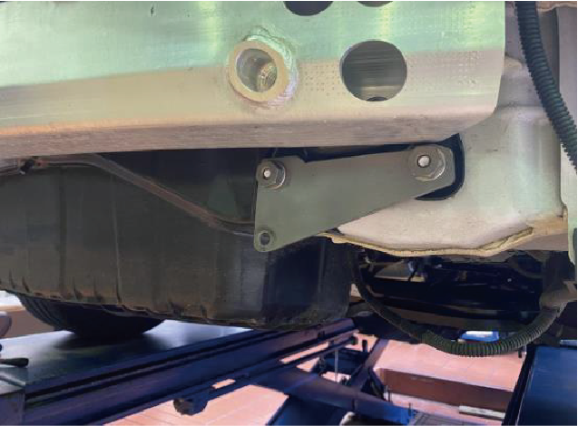
#4
Fix the Brackets
Refer to the image and tighten the "4.bracket (for rear)" with "12.color" "13.Special nuts" and existing bolt on the body side.
Check the overall balance and assembly condition, etc., and fix it securely of each bolt.
(Torque Value: 63.5 Nm)

#5 (Performance & RWD Only)
Fix the BODY DAMPER
for Performance & RWD Model Only
<Attention!> Watch the mounting position of the spacer!
Referring to the image, assemble "2.Body (for rear)" with "9.M10×30 Hex bolt”, "10.Spacer" "11.Nut" and tighten both sides.
(Temporary Torque Value: 45Nm)

#5 (LongRange Only)
Fix the BODY DAMPER
for Performance & RWD Model Only
<Attention!> Watch the mounting position of the spacer!
Referring to the image, assemble "2.Body (for rear)" with "9.M10×30 Hex bolt”, "10.Spacer" "11.Nut" and tighten both sides.
(Temporary Torque Value: 45Nm)
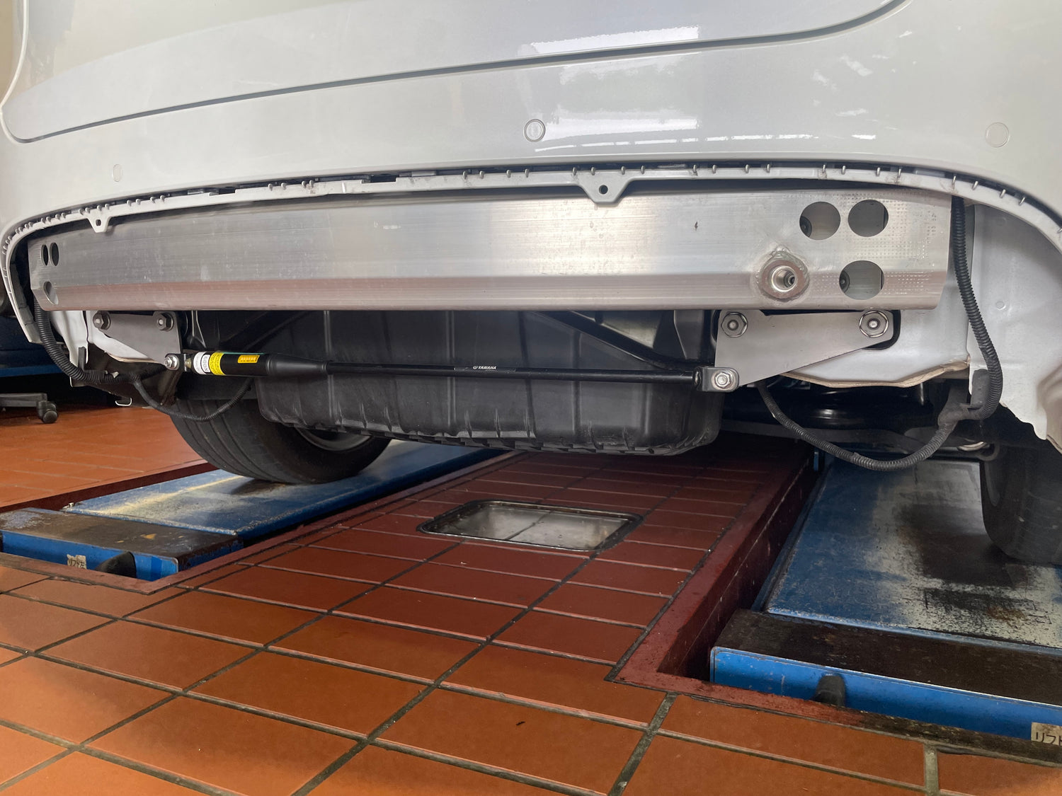
Final check
Check the overall balance, assembly condition, etc., and fix the bracket securely according to the Torque Value of each bolt.
<- Final Image